


Certificate Of Origin (C/O) And Quality (C/Q) For Heavy Duty Cranes
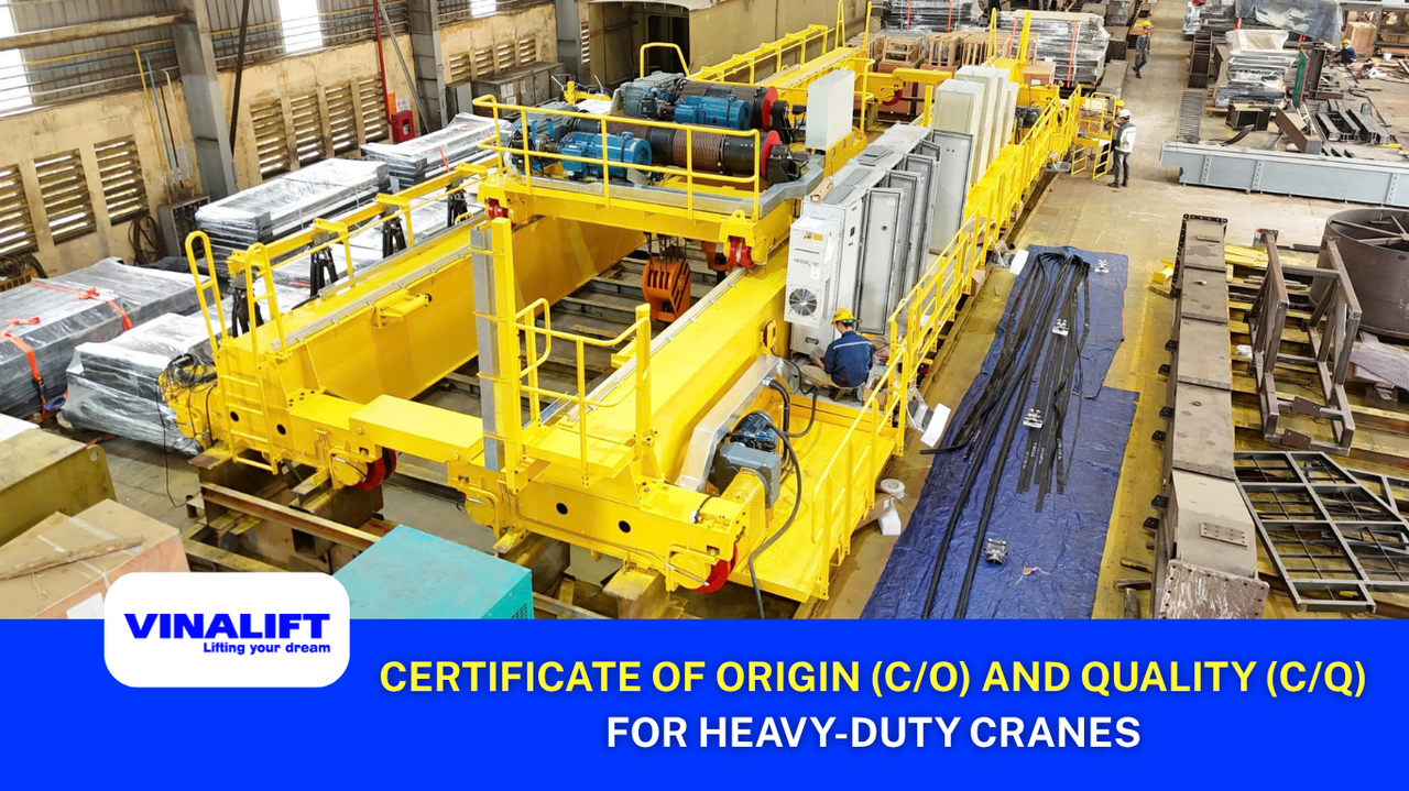
Jul
An EPC Director whose payment has once been suspended because the C/O documentation for a hydraulic brake assembly was invalid will never allow the same situation to happen again.
This is not an uncommon situation. In large-scale steel projects, the owner’s independent inspection consultant has the authority to suspend the entire FAT/SAT acceptance process if any load-bearing component lacks a valid Certificate of Origin – even when the equipment has already been delivered to the project site, the installation team has been fully mobilized, and only a few weeks remain before the project handover deadline. The costs resulting from such a suspension – including storage, idle labor, and delay penalties – can completely eliminate the profit margin of the equipment supply package.
This article from VINALIFT analyzes which core components of a heavy-duty overhead crane must be supplied with complete Certificate of Origin (C/O) and Quality (C/Q) for heavy-duty cranes, why the absence of just one required certificate is sufficient to delay an entire EPC project, and how VINALIFT controls this risk from the bidding stage.
Crane acceptance and operational risks
Zero-failure tolerance pressure
In metallurgical plants, a metallurgical crane serves as the backbone of the entire molten material handling process. The equipment operates continuously, 24 hours a day, 7 days a week, under direct thermal radiation from molten steel ladles at temperatures ranging from 1,500°C to 1,600°C, highly abrasive slag dust, corrosive acidic gases (SO₂ and NOₓ), and electrically conductive graphite dust. Any unplanned shutdown of a ladle crane results in losses of thousands of dollars per hour and, more critically, may lead to catastrophic molten steel spills that can cause explosions and fires within the plant.
Under these extreme operating conditions, conventional industrial cranes cannot satisfy the requirements of metallurgical service. The crane should be classified under FEM 1.001 using Utilization Class U and Load Spectrum Class Q, typically reaching FEM A6 to A8 depending on the application, while structural design and load calculations should comply with EN 13001. Metal fatigue accumulation or electrical cabinet short circuits caused by conductive dust can destroy the operating mechanism within only a few weeks if the equipment is not equipped with multiple layers of engineering protection from the design and manufacturing stages.
Why is FEM 1.001 an irreplaceable standard for steel mill crane applications?
FEM 1.001 is not simply a certificate displayed on the wall. It is the mandatory fatigue life calculation method for any lifting equipment operating under repeated high-intensity loading conditions. The fundamental difference compared with conventional design standards is that FEM 1.001 requires manufacturers to calculate the structural design based on the total number of actual operating cycles throughout the equipment’s service life, rather than relying only on the maximum static load.
In a steel plant, a ladle crane operating three shifts per day may accumulate millions of lifting cycles over a 20-year service life. If the main girder and primary load-bearing welds are not designed in accordance with the A6 to A8 duty classifications specified by FEM 1.001, metal fatigue will accumulate gradually and may only become visible as cracks in the main girder after 18 to 24 months of operation — by which time the repair cost and associated risks have far exceeded the initial savings gained from selecting a lower-cost supplier.
When requesting a manufacturer to demonstrate compliance with FEM 1.001, an EPC Director should specifically require the structural fatigue calculation report—not merely the design drawings—the Class of Utilization and Load Spectrum Factor calculations for each mechanism, and the 100% Ultrasonic Testing (UT) procedure for the main girder welds. Without any one of these documents, a claim of “FEM compliant” is merely marketing language.
Why does the absence of C/O and C/Q documentation for core components delay EPC projects?
One of the most common reasons EPC contractors experience suspended payments or project handover delays is incomplete or unclear C/O and C/Q documentation documentation (C/O – Certificate of Origin and C/Q – Certificate of Quality). In large-scale steel projects, project owners always appoint independent inspection consultants to supervise every stage of technical acceptance (FAT/SAT) with rigorous requirements.
If a critical load-bearing or power transmission component does not have a clearly traceable origin from qualified suppliers or lacks an independent quality certification, the entire crane system will be rejected during site acceptance. This risk not only delays the overall EPC project schedule but also increases storage costs, labor expenses, and unplanned maintenance costs.
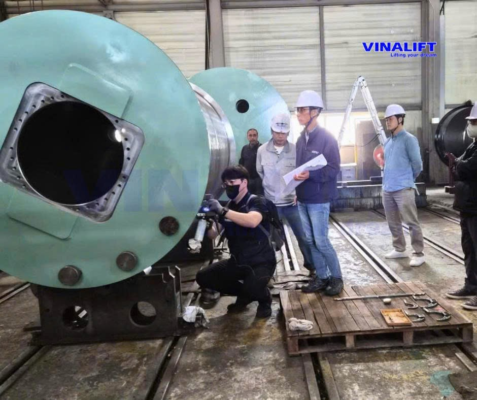
Components requiring certificates
Motors and gearboxes
For a steel plant crane used to lift steel ladles, steel billets, and steel coils to operate reliably, the entire main drive system shall be equipped with genuine imported core components from G7 countries. Heavy-duty AC motors shall meet Class H insulation requirements (high-temperature resistance with independent forced cooling) and be equipped with high-quality encoder speed sensors from manufacturers such as Siemens (Germany) or ABB (Switzerland).
Industrial gearboxes shall use monobloc cast iron housings with a gearbox service factor greater than 1.5, capable of withstanding extremely high impact loads, and be supplied by reputable manufacturers such as Flender or SEW-Eurodrive. All of these components shall be accompanied by valid C/O documentation issued by the competent authority and C/Q or factory test certificates confirming successful no-load testing and quality compliance.
Braking system and hoisting mechanism
The safety of a metallurgical crane is based on a single-failure-proof design with a redundant load path, also known as the Single-Failure Proof principle. Unlike conventional suspension cranes, heavy-duty hoisting mechanisms require a two-level braking system.
- Service brakes: Service brakes shall always consist of two independent brake units installed on the high-speed shaft before the gearbox. Each brake shall provide a minimum braking torque equal to 150% of the motor’s rated torque, ensuring that if one brake fails, the remaining brake is still capable of holding the entire load.
- Emergency brakes: Emergency brakes use hydraulic disc caliper brake assemblies (such as Sibre or Pintsch Bubenzer) acting directly on the rope drum flange.
This braking system operates according to the Fail-Safe principle, automatically locking the rope drum through mechanical spring force in the event of a complete power failure or an overspeed condition exceeding 115% of the rated speed. Every component of the hydraulic braking system shall be supported by static and dynamic load test documentation before being included in the final technical acceptance dossier.
Laminated hook assembly and wire rope
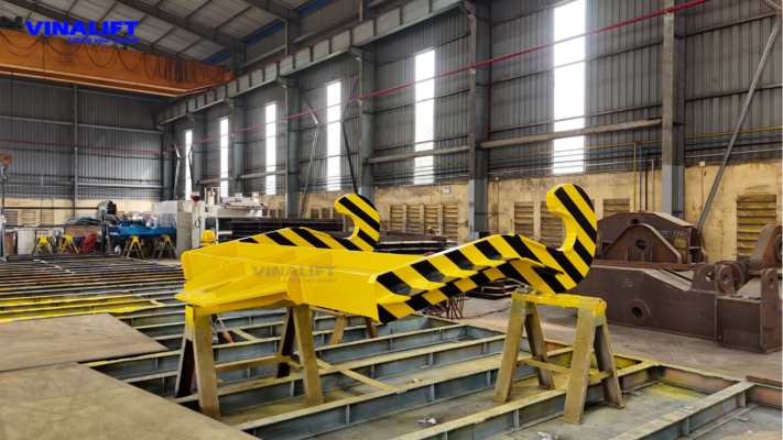
In Double girder ladle crane and four-girder ladle crane designs, the main hook assembly is designed as a hook beam supporting two laminated hooks manufactured from multiple thin structural steel plates connected by rivets instead of a single forged steel hook to eliminate the risk of sudden fatigue crack propagation caused by thermal shock.
The wire rope used for the hoisting mechanism shall be Independent Wire Rope Core (IWRC) heat-resistant wire rope (such as Casar or Teufelberger), lubricated with high-temperature grease to prevent lubricant dripping. The complete laminated hook assembly and wire rope shall be supplied with Certificate of Origin (C/O) and Quality (C/Q) for heavy-duty cranes, together with breaking load test reports issued by internationally accredited laboratories.
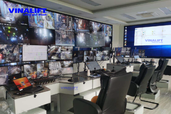
Variable frequency drive and CMS monitoring system
The electrical control system of a metallurgical crane shall be installed inside a fully enclosed E-Room with a minimum protection rating of IP54 to IP66, maintaining positive pressure to prevent electrically conductive graphite dust from entering and causing short circuits in the control system.
The core control solution includes a VFD closed-loop vector control system with torque proving, which verifies motor torque before brake release to prevent rollback or load drift. In addition, the Active Front End (AFE) regenerative system returns the energy generated during load lowering back to the plant power grid, eliminating the need for high-power braking resistors mounted on the crane girder.
The Crane Management System (CMS) continuously runs an integrated algorithm to calculate the actual fatigue life of the wire rope and girder structure in accordance with ISO 12482 (Predictive Maintenance). This enables maintenance engineers to receive early warnings when the wire rope or girder structure approaches the Safe Working Period (SWP) limit, typically when only 10–15% of the design life remains, allowing replacement to be scheduled during planned shutdowns and significantly reducing the risk of unexpected wire rope failure.
Standards applied in inspection and manufacturing
Heavy-duty cranes girder design
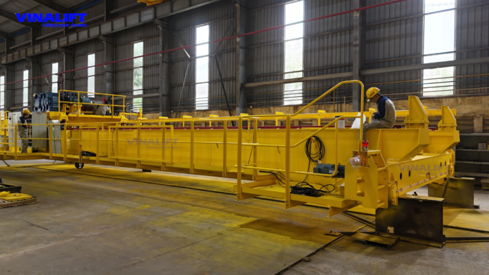
The design of a heavy-duty cranes girder operating under severe fatigue conditions cannot be based on conventional static calculations. It shall strictly comply with FEM 1.001 or EN 13001 fatigue design standards. The main girder structure shall be a welded box girder fabricated from high-strength steel plates and reinforced with internal diaphragms to prevent local buckling and girder twisting during molten steel ladle handling.
Multiple-layer heat shields filled with 50 mm to 100 mm ceramic fiber insulation shall always be installed beneath the main girder to maintain the structural steel temperature below the 70°C safety limit, preventing steel degradation and unintended girder deflection.
Non-destructive testing procedure
All primary load-bearing welded joints between the main girder flange plates and the end carriages/end trucks shall be full-penetration welds performed by internationally certified welders.
The manufacturing quality control procedure requires 100% Ultrasonic Testing (UT) together with Magnetic Particle Testing (MT) to detect microcracks, porosity, or slag inclusions inside the welds. These NDT reports form the core technical documentation of the C/Q package delivered together with the equipment.
VINALIFT Manufacturing Capability
ISO 9001:2015 crane manufacturing plant
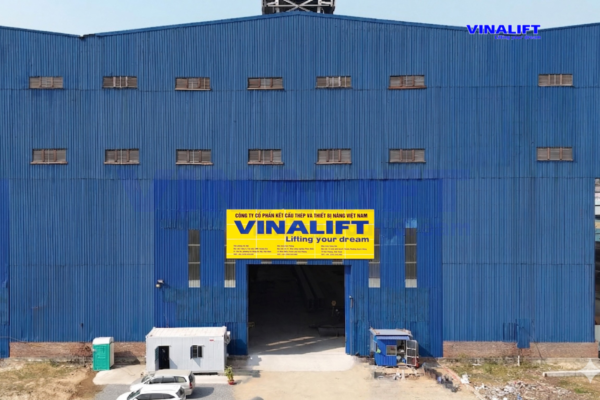
In Vietnam, VINALIFT (VINALIFT Lifting Equipment and Industrial Construction Joint Stock Company) is proud to be an ISO 9001:2015 crane manufacturing plant with well-established production capabilities. Equipped with modern manufacturing facilities, including large-format CNC plasma cutting machines, automatic gantry welding systems, and a surface preparation line capable of achieving the Sa 2.5 cleanliness standard before the application of high-performance anti-corrosion epoxy coating in accordance with EN ISO 12944 C4/C5, VINALIFT is a trusted domestic partner of reputable EPC contractors in Vietnam and overseas.
Representative Projects:
Steel Industry – 40/10 t double-girder overhead crane – Argentina Steel Plant
Background: The customer is a top-tier global metallurgical industrial group developing a production line in South America—a market where technical standards and acceptance procedures are implemented strictly in accordance with international standards, with no exceptions for suppliers from emerging markets.
Challenge: The customer required every crane to complete a full no-load trial run at the VINALIFT factory before packaging, with direct inspection by the customer’s representatives. The total shipment weighed hundreds of tonnes, requiring a dedicated packing, crating, and ocean logistics plan.
Implementation: The project was directly supervised by Technical Director Vu Khac Diep and Production & Quality Director Vu Dinh Tu, from engineering design through the inspection of every weld. All five crane systems successfully completed the no-load test, were packed using dedicated export packaging, and were shipped to Argentina by sea on schedule. The equipment complies with FEM A6 duty classification, with mechanisms designed for the corresponding M6 mechanism group where applicable, and provides IP55 protection.
(Read the full project story:VINALIFT and the Journey to Cement Its Position in the Global Market)
80/20 t double-girder overhead crane | Specialized Lifting Solution for Metallurgical Plants
- Duty Classification: A6/M6
- Span: 19 m
- Lifting Height: 20/24 m
- Operating Environment: Up to 60°C
Cost Optimization Solution and Commitment to Complete C/O and C/Q Documentation
VINALIFT’s competitive advantage does not come from reducing component costs. It comes from complete control over both ends of the value chain: detailed engineering design and structural fabrication are carried out in-house by engineers trained in accordance with European standards, while all core components—including motors, gearboxes, emergency brakes, variable frequency drives, and PLCs—are imported from G7 brands with complete customs C/O documentation and genuine C/Q certificates.
This combination delivers something that overseas manufacturers cannot provide: a site response time of within 24 hours, supported by spare parts readily available in Vietnam, significantly reducing waiting time compared with ordering replacement parts from manufacturers in China or South Korea when unexpected failures occur.
For an EPC Director, this means a commitment that can be incorporated into the contract: complete Certificate of Origin (C/O) and Quality (C/Q) for heavy-duty cranes documentation for 100% of all core components, ready for FAT/SAT.
Conclusion
Whether for an EPC project involving a steel plant, power plant, deep-water port, or heavy industrial complex, when a heavy-duty overhead crane operates continuously 24/7 at its rated capacity in a harsh environment, the boundary between safe operation and catastrophic failure does not lie in its lifting capacity. It lies in every Certificate of Origin (C/O) and Quality (C/Q) for heavy-duty cranes provided for each critical component.
Requiring and strictly controlling the origin and quality documentation from the equipment procurement stage, rather than waiting until FAT/SAT at the project site, is a key technical measure for controlling schedule risks, protecting the right to claim compensation in the event of failures, and ensuring an on-time project handover to the project owner.
As a Vietnamese manufacturer of heavy-duty craness designed in accordance with FEM 1.001 and EN 13001, VINALIFT is committed to providing complete quality documentation for 100% of imported core components from independently verified European suppliers, eliminating the risks of suspended payments and delays in technical acceptance for international EPC projects.
Request a sample C/O and C/Q documentation package and a 30-minute technical review with a VINALIFT engineer
If you are preparing tender documentation or developing technical acceptance criteria for a heavy-duty cranes project, the VINALIFT engineering team is ready to provide a sample C/O and C/Q documentation package from completed projects and work directly with you to determine the inspection requirements that match the project owner’s acceptance criteria.
Hotline: (+84) 39 341 6686
Email: contact@vinalift.vn
