


Ladle Crane Factory Acceptance Test Procedure for EPC
Jul
An EPC Director who has committed to delivering a steel plant on schedule has very few options when critical lifting equipment fails at the project site. It is not because the project lacks the budget to resolve the problem — it is because there is no time left.
The cost of shutting down a steelmaking furnace is estimated at USD 10,000–50,000 per hour. A defective main girder weld that goes undetected during manufacturing may only become apparent after hundreds of lifting cycles at the job site. By that stage, repairs performed 20 meters above ground in an environment filled with abrasive slag dust and extreme thermal radiation may cost five to ten times more than correcting the issue at the manufacturing facility. Likewise, a braking system that has not been verified through the correct testing procedure can lead to an irreversible catastrophe.
This article from VINALIFT provides a detailed analysis of the Ladle crane Factory Acceptance Test (FAT) procedure in accordance with European standards — the most effective technical risk management tool an EPC Director can require before equipment leaves the manufacturing plant.
The importance of Factory Acceptance Testing
In integrated metallurgical plant projects, a steel plant crane is far more than auxiliary equipment — it is the backbone that sustains the entire production process. Any failure involving this equipment at the project site may delay the commissioning schedule and result in enormous financial losses, estimated at tens of thousands of dollars for every hour of furnace downtime.
For this reason, the ladle crane Factory Acceptance Test (FAT) procedure serves as the ultimate technical safeguard. FAT enables EPC contractors to identify and eliminate manufacturing defects, mechanical assembly errors, electrical panel wiring issues, and control algorithm deficiencies while the equipment is still at the manufacturer’s facility.
Resolving these issues under standard factory conditions is always faster, safer, and significantly more cost-effective than performing repairs 20 meters above the steelmaking workshop floor, where abrasive dust and intense thermal radiation create an extremely harsh working environment.
Design and manufacturing standards applied during the FAT procedure
Ultra-heavy lifting equipment operating in the “hellish” environment of a steel plant requires exceptionally stringent engineering standards. To ensure long fatigue life, the crane manufacturer shall determine the Utilization Class U8 and Load Spectrum Class Q4 in accordance with FEM 1.001, resulting in an A8 duty classification where applicable. Structural design and load calculations shall comply with EN 13001.
The FAT procedure shall be established through the close integration of European mechanical engineering standards and a comprehensive quality management system. Every stage—from incoming steel material inspection and full penetration welding procedures to load testing and electrical system integration—shall be controlled under an ISO 9001:2015-certified quality management system.
This ensures consistent technical data throughout the manufacturing process while minimizing future operational risks.
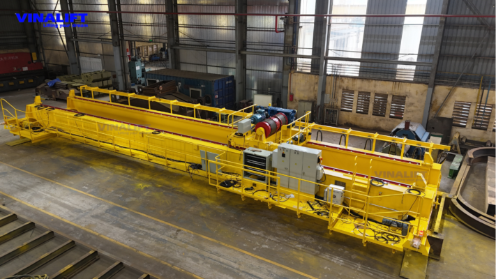
Ladle crane Factory Acceptance Test (FAT) procedure
Step 1: Inspection of steel structure, geometric dimensions, and main girder quality documentation
The first stage of the FAT procedure focuses on verifying the structural integrity of the crane girder. Designing a heavy-duty crane girder requires a welded box-girder configuration incorporating anti-torsional internal diaphragms spaced at intervals of 1.0 m to 1.5 m.
The EPC inspection engineer shall perform the following verification activities:
- Review of Non-Destructive Testing (NDT) documentation: verify all Ultrasonic Testing (UT 100%) and Magnetic Particle Testing (MT) results for the primary load-bearing welds connecting the main girder flange plates, ensuring complete weld penetration.
- Geometric dimension inspection: verify the girder span, trolley rail centerline alignment, and designed main girder deflection to compensate for elastic deformation under heavy lifting conditions.
- Inspection of the thermal protection system: verify the configuration of the heat shields installed beneath the main girder. The heat shield assembly shall incorporate either an air gap or 50–100 mm thick ceramic fiber insulation, ensuring that the temperature of the girder bottom flange remains below the safe operating limit of 70°C when exposed to a 1,600°C molten steel ladle.
Step 2: Testing of the hoisting mechanism and redundant drive system
For metallurgical crane applications operating in casting areas, the single-failure-proof philosophy is a mandatory engineering requirement. Both charging crane and ladle crane systems shall be designed with an independent dual-rope reeving system.
The FAT procedure shall simulate a wire rope failure scenario to verify the response of the mechanical system.
- Simulated wire rope failure: When one wire rope is suddenly severed, the tension in the remaining rope immediately doubles. The inspection engineer shall verify the movement of the equalizer bar and the response of the imbalance detection system.
- Safety interlock verification: The imbalance condition shall activate the safety limit switches. The electrical signal shall be transmitted to the central PLC within less than 10 ms to trigger Emergency Stop (E-Stop) command and activate the emergency caliper brake to lock the rope drum.
- Drive redundancy test: The inspection engineer shall intentionally disconnect one of the main hoisting motors to simulate a motor failure during actual operation. The system shall automatically switch to half-speed mode through the redundant variable frequency drive and either a planetary gearbox or differential gearbox.
- Acceptance criterion: The crane shall remain capable of transporting the molten steel ladle to a designated safe location before coming to a complete stop.
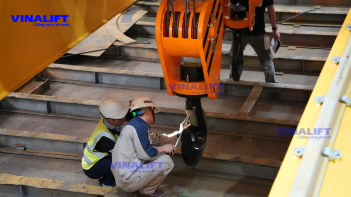
Step 3: Verification of the independent two-tier safety braking system
The FAT procedure shall include comprehensive verification of the two-tier braking system operating under the Fail-Safe principle (spring-applied, hydraulically/electrically released).
Level 1 (Service Brakes): Installed on the motor high-speed shaft, consisting of two independent brake units, each providing a minimum braking torque equal to 150% of the rated motor torque.
Level 2 (Emergency Brakes): Hydraulic Caliper Brakes acting directly on the Rope Drum Flange. The emergency brake shall be tested for automatic activation under the following conditions:
- Overspeed exceeding 115% of the rated speed.
- Wire rope failure.
- Sudden power loss.
- Manual Emergency Stop (E-Stop) activation by the operator.
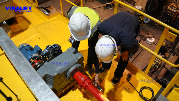
Step 4: Static and dynamic load testing in accordance with European standards
This stage provides the most direct demonstration of the fatigue load capacity of the steel structure and the performance of the drive system. Load testing shall be continuously monitored using Load Pins installed on the equalizer pulley.
- Static Load Test: Conducted at 125% of the Safe Working Load (SWL). The test load shall be lifted approximately 100–200 mm above ground and held for 10 minutes. During this period, the inspection engineer shall measure the elastic deflection of the main girder and verify the absence of cracks, permanent deformation, or oil leakage from gearboxes and hydraulic braking systems.
- Dynamic Load Test: Conducted at 110% of the Safe Working Load (SWL). The crane shall repeatedly perform lifting, lowering, and travelling operations to evaluate the stability of the Independent Drives together with the performance of the Cellular/Hydraulic Buffers installed at the end of the runway.

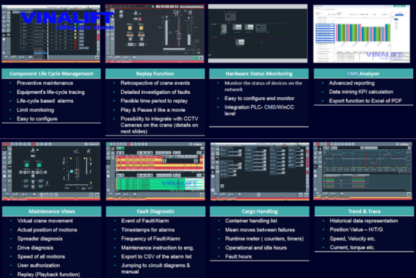
Step 5: Testing of the intelligent control system, CMS, and predictive maintenance functions
In the era of Industry 4.0, EPC contractors increasingly prioritize lifting equipment integrated with intelligent control technologies. During the FAT session, all core software functions shall be configured and tested under simulated operating conditions.
- VFD closed-loop vector control and torque proving: verify the Zero Rollback function, ensuring that no load drift or vibration occurs when lifting a molten steel ladle.
- Sensorless anti-sway system: the PLC-integrated control algorithm automatically adjusts the acceleration profile according to the current wire rope length, eliminating load sway inertia so that the molten steel ladle stops in a completely stable position.
- Absolute positioning system: using a stainless-steel Barcode Positioning System (BPS) with coded markers installed along the crane runway and dedicated infrared readers, achieving positioning accuracy of ±1 mm to ±5 mm. This function enables the PLC to establish virtual No-Fly Zones protecting sensitive areas such as substations and central control rooms.
- Crane management system (CMS): Crane Management System (CMS): verify that the CMS collects load and operating cycle data and calculates the remaining Safe Working Period (SWP) in accordance with ISO 12482, and displays the remaining fatigue life of wire ropes and gearboxes directly on the HMI.
VINALIFT’s FAT Execution Experience and Capability
As a crane manufacturer with an ISO 9001:2015-certified quality management system, VINALIFT has implemented comprehensive Factory Acceptance Test (FAT) procedures in accordance with European standards for actual ladle crane projects in Vietnam.
Representative projects:
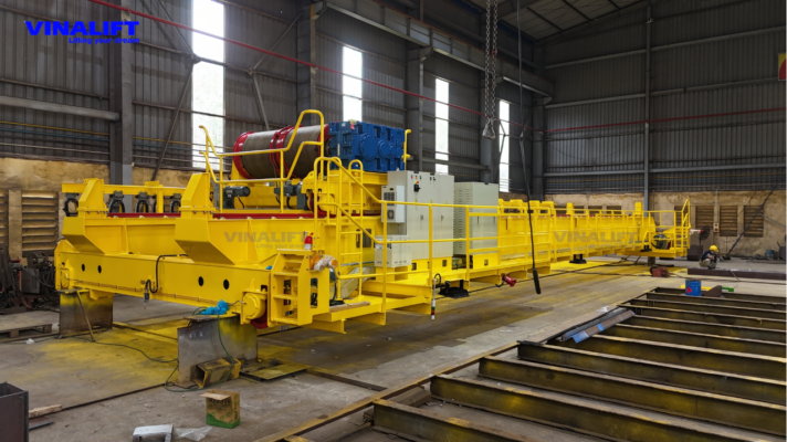
Steel Industry – 75/20 t ladle crane – Hoa Phat Steel Plant
- Span: 19.5 m | Lifting Height: 19 m | Duty Class: A8 (FEM 1.001)
- Application: Lifting and pouring molten steel in the steelmaking furnace area. This ladle crane operates under the ultra-heavy-duty A8 classification.
The FAT procedure carried out at the VINALIFT manufacturing facility includes:
- Static load testing at 125% SWL witnessed by an independent third-party inspector.
- 100% UT inspection of all main girder welds.
- Demonstration of the Sensorless Anti-Sway algorithm and the Absolute Positioning system on the PLC/HMI before shipment.
VINALIFT maintains a spare parts inventory in Vietnam together with an on-site technical service team, enabling significantly shorter response times than overseas manufacturers that must import replacement parts upon order.
Conclusion
The ladle crane Factory Acceptance Test (FAT) procedure is not merely an administrative acceptance procedure. It is the most effective technical and schedule risk management tool for EPC contractors. Investing properly in the FAT stage helps minimize system failures that may occur during installation at a metallurgical plant site.
To achieve absolute operational safety and improve the efficiency of molten metal flow from scrap charging to billet casting, selecting a manufacturing partner with in-depth expertise in FEM 1.001 and proven FAT capability, such as VINALIFT, is a strategic decision. VINALIFT’s crane designs for steel plants not only meet the requirements for lifting steel billets and coils but also provide integrated engineering solutions with intelligent automation technologies, giving EPC contractors complete confidence.
From its manufacturing facility in Vietnam to steel plant projects in South America, VINALIFT is contributing to the global presence of Vietnamese industrial engineering. Every FAT procedure is carried out not simply to satisfy a procedural requirement, but to reduce the risk that lifting equipment defects could delay commissioning or disrupt the project schedule.
Request the FAT checklist template and a 30-minute technical review with a VINALIFT engineer
If you are preparing technical documentation for the FAT stage or need to evaluate a manufacturer’s capability before tendering, the VINALIFT engineering team is ready to work directly with you by providing a European-standard FAT checklist and a project-specific technical risk review.
Hotline: (+84) 39 341 6686
Email: contact@vinalift.vn
