


Single-Failure Proof Philosophy
Jul
Throughout the history of heavy industrial accidents, most disasters involving lifting equipment have not occurred because the entire system failed simultaneously. They occurred because a single component failed and there was nothing to back it up.
When a ladle crane is lifting 150 tonnes of molten steel at 1,600°C, that scenario is no longer merely an engineering risk. It becomes an irrecoverable disaster: molten steel spills, the workshop catches fire, the production line comes to a complete stop, and the EPC project schedule collapses in a chain reaction. The cost of a load-drop accident in a metallurgical environment is measured not by the cost of repairing the crane, but by the total loss incurred by the entire project.
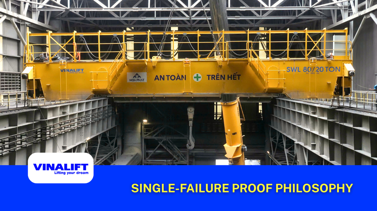
That is why a modern steel mill crane must never be designed with a single point of failure. This article from VINALIFT provides a detailed analysis of the single-failure proof philosophy.
The core principle of this philosophy is:
No single failure shall be allowed to result in the loss of load-holding capability.
Single point of failure – the greatest design risk in a metallurgical crane
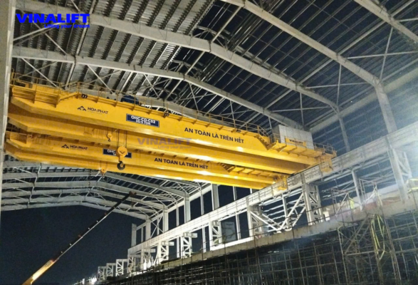
In systems engineering, a single point of failure is any component whose failure causes the loss of a critical function of the entire system.
For a crane lifting molten steel, single points of failure often appear in:
- Hoisting rope system.
- Braking mechanism.
- Drive system.
- Gearbox.
- Load transmission path.
- Control power supply system.
In a conventional industrial crane, the consequence of these failures is usually an operational shutdown. For a steel mill crane, the consequence may be load loss. That is why the entire mechanical architecture is built on the principle of eliminating single points of failure from critical load-bearing and load-holding components.
Failure scenario 1: Hoisting rope breakage
Rope breakage is one of the first scenarios considered in heavy-duty crane design. If the entire load is suspended from a single force transmission path, a rope break will immediately lead to load loss.
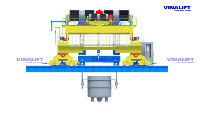
To eliminate this risk, steel mill crane systems apply a dual rope reeving architecture combined with an equalizer bar.
In this architecture:
- The load is distributed across multiple independent rope falls.
- Hoisting force does not depend on a single load path.
- The system can still maintain load-holding capability when one rope fall fails.
This is the foundation of the redundant load path concept. The design objective is not to prevent the rope from breaking, but to ensure that the load does not fall when the rope breaks. These are two completely different ways of thinking.
See more: [Heavy-Duty Crane Manufacturer Capability Checklist for EPC] – criteria 3 and 4 in the checklist are directly related to redundant load path architecture and braking systems.
Failure scenario 02: Loss of braking capability
For a molten steel lifting system, brakes are the final protective layer between the load and gravity. If the hoisting mechanism loses torque but the brakes can still hold the load, the system remains safe. If the brakes lose their load-holding capability, nearly every upstream component becomes meaningless.
To address this critical weak point, metallurgical safety standards require the following brake configuration:
Layer 1: Service Brakes / Duty Brakes
- Position: Still mounted on the motor shaft, or high-speed shaft.
- Quantity: Always two independent brake sets for one hoisting mechanism. Each brake set must be designed with a braking torque of at least 150% of the rated motor torque. If one brake set fails, the remaining brake set still has more than enough capacity to hold 150% of the load.
- Function: Used for braking and holding loads during normal daily lifting and lowering operations.
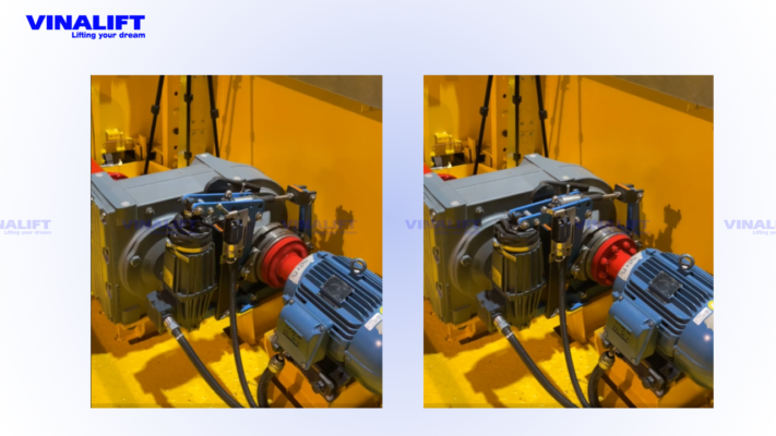
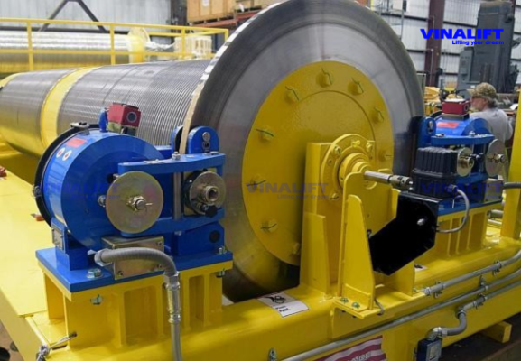
Layer 2: Emergency Caliper Brakes
- Position, which is extremely important: mounted directly on the rope drum flange – the slowest-speed shaft but also the shaft with the highest torque.
- Brake type: Giant hydraulic caliper disc brakes. They are designed to clamp directly onto the rope drum flange, providing an independent braking layer on the low-speed, high-torque side of the hoist..
- Function: They remain on standby. If the drive system breaks, or if the lowering speed exceeds the safe limit, this brake assembly will clamp directly onto the drum and lock it immediately. The load cannot fall even if the gearbox is completely destroyed.
Failure scenario 03: Hoist drive failure
In heavy-load lifting systems, loss of drive torque is one of the situations with a high probability of occurring during the equipment life cycle.
The cause may come from:
- Motor failure.
- VFD / frequency inverter failure.
- Coupling failure.
- Gearbox failure.
If the system uses only one drive source, every failure leads to loss of hoisting function.
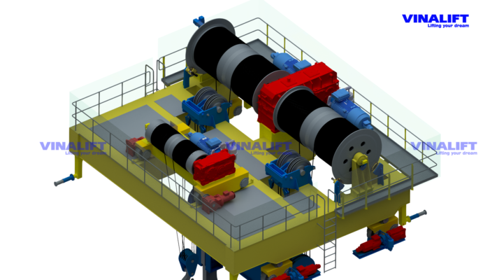
To solve this problem, metallurgical crane systems often apply dual drive architecture.
In this configuration:
- Multiple drive mechanisms participate in carrying the load.
- The load is distributed across multiple torque sources.
- The system reduces dependence on a single drive assembly.
The objective is to increase the ability to maintain a safe state when a failure appears, rather than to increase capacity.
Failure scenario 04: Power loss or control system loss
For a ladle crane, power loss is not simply a utility failure.
It is a mandatory design scenario that must be considered.
Under real operating conditions, power loss may originate from:
- Grid failure.
- Distribution system fault.
- Inverter fault.
- Control system fault.
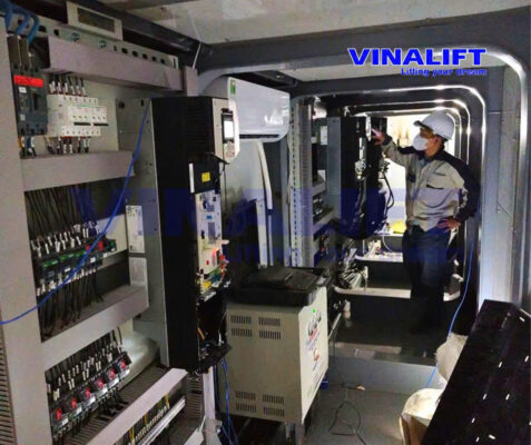
Therefore, modern systems often apply a highly redundant control and monitoring architecture, combined with independent mechanical protection layers, to ensure load-holding capability even when power is no longer maintained.
This is why modern ladle crane systems are no longer purely mechanical machines, but integrated electromechanical systems with multiple independent protection layers.
Single-failure proof architecture for ladle cranes
The Single-Failure Proof Philosophy is not created by one single technology. It is a multi-layer architecture – in which each layer operates independently and can immediately take over when the previous layer fails.
Layer 1 – Redundant Load Transmission Path
Instead of a single force transmission path from the drum to the hook, the ladle crane system is designed with multiple parallel load paths. When any transmission path breaks or becomes jammed, the load is still held by the remaining branch. This is the foundational principle of redundant structure under EN 13001 — the European standard for metallurgical crane safety.
Layer 2 – Dual Rope Reeving System
The dual rope reeving architecture distributes the load across multiple independent rope falls. The equalizer bar balances force between the falls, preventing one fall from carrying an uneven load that could lead to premature rope breakage. For ladle crane applications, the hoisting rope system is typically specified for the highest FEM duty group, such as A8/M8, together with a severe load spectrum such as Q4. The rope safety factor should be verified against the applicable project standard and manufacturer calculation, rather than assumed from the duty class alone.
Layer 3 – Dual Drive Architecture
Each hoisting mechanism is equipped with two independent drive systems — two motors, two VFDs / frequency inverters, and two gearboxes. When one drive assembly loses torque, the other takes over immediately without allowing the load to fall freely. This design improves the ability of the hoisting system to maintain a safe state under drive failure and is consistent with the severe-service expectations of CMAA Class F applications, where cranes may operate continuously under demanding duty conditions.
Layer 4 – Multi-Layer Braking System
Three braking mechanisms operate hierarchically: Service Brake — normal working brake; Holding Brake — holding the load when the hoisting mechanism stops; Emergency Caliper Brake — acting directly on the rope drum flange when the primary braking layers lose load-holding capability. The entire system is designed according to the fail-safe design principle: power loss → brake automatically closes, without requiring a control signal.
See also: [European-Standard Ladle Crane Acceptance Testing Procedure for EPC] — including the practical inspection procedure for the two-layer braking system during FAT.
Layer 5 – Emergency Load-Holding Mechanism
In addition to the braking system, some ladle crane designs integrate a mechanical drum-locking mechanism — activated independently of the electrical and control systems. This mechanism ensures that the load is held even in a scenario where total power loss occurs simultaneously with brake failure.
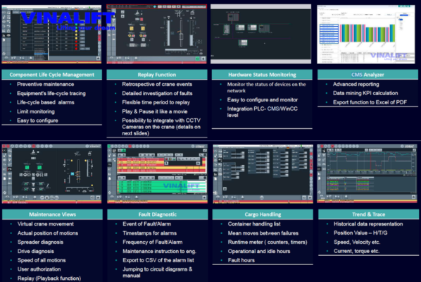
Layer 6 – Equipment Condition Monitoring
The CMS continuously monitors winding temperature, bearing vibration, brake status, and rope wear. According to ISO 12482, the system issues early warnings before parameters exceed the safe threshold — shifting from reactive maintenance to predictive maintenance. This is a condition for a ladle crane to operate 24/7 under the FEM A8/M8 cycle without increasing cumulative risk over time.
This is the foundational architecture of the anti-single-failure design concept in modern metallurgy — not a list of additional features, but a multi-layer defense system designed to ensure that a single failure never becomes a disaster.
The role of FEM A8/M8 in ladle crane design
Steel mill crane systems do not only carry heavy loads.
They also operate at extremely high frequency in harsh high-temperature environments.
That is why most ladle crane systems are designed according to FEM A8/M8 duty class combined with load spectrum group Q4.
These duty classes reflect:
- Continuous operating cycles.
- Extremely heavy load levels.
- High reliability requirements.
- Long-term equipment service life.
In a metallurgical environment, compliance with FEM is not merely a structural requirement.
It is a reliability requirement for the entire crane safety architecture.
Evidence from VINALIFT metallurgical projects
Practical implementation shows that the anti-single-failure philosophy does not exist only on design drawings.
It appears in large-scale metallurgical projects.
VINALIFT’s steel industry project portfolio includes:
Steel industry — 40/10 t double girder overhead crane — Argentina steel plant.
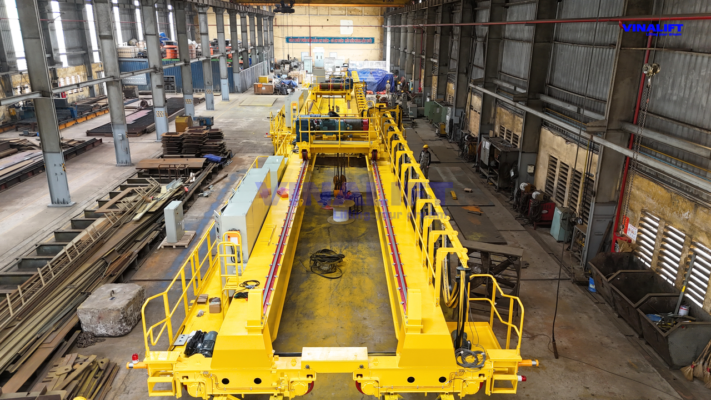
These projects all belong to the application group with the highest safety requirements in the metallurgical industry.
Here, engineering capability is not evaluated by nominal lifting capacity, but by the ability to maintain a safe state when a critical component fails.
That is also the essence of the Single-Failure Proof Philosophy.
Conclusion
In ladle crane design, the engineering objective is not to completely eliminate the possibility of failure.
The objective is to ensure that failure does not lead to load loss.
This philosophy has created architectures such as:
- Redundant Load Paths
- Dual Drive Architecture
- Redundancy System
- Dual Rope Reeving
- Emergency Caliper Brake
- Condition Monitoring
These are not additional features. They are protective layers built to ensure that a single failure cannot develop into a catastrophic incident. For the metallurgical industry, this is not only a design requirement. It is a mandatory condition for a lifting system to be permitted to operate.
From the manufacturing workshop in Vietnam to steelmaking plants in South America, VINALIFT is proving that single-failure proof design is not an exclusive privilege of European manufacturers. Every crane leaving the factory is a commitment made with engineering and honor: your production line will never stop because of a single point of failure that we could have prevented from the design stage.
Request a sample technical specification for a single-failure proof ladle crane
If you are preparing a technical specification or evaluating the safety architecture of lifting equipment for a steel plant project, VINALIFT’s design engineering team is ready to provide practical technical documents – including the single-failure proof philosophy architecture diagram, FEM fatigue factor calculation sheet, and multi-layer braking system solution – and work directly with you to assess the specific design risks of your project.
- Hotline: (+84) 39 341 6686
- Email: contact@vinalift.vn
