


Multi-Layer Braking Protection for Ladle Crane Load-Holding Safety
Jul
Most load-loss incidents in the operating history of metallurgical crane systems did not occur because the brakes were not strong enough. They occurred because the brakes were installed in the wrong position — and when the gearbox failed, the brake on the motor was still closed while 150 tonnes of molten steel at 1,600°C below had completely lost connection with the load-holding system.
That is the scenario no EPC Director wants to explain to the project owner. It is also why FEM 1.001 does not allow ladle crane design to rely on only one single protection point — no matter how strong that point is.
This article by VINALIFT analyzes the Multi-Layer Braking Protection architecture in a ladle crane — why two independent braking layers are required, why the second layer must clamp directly onto the drum instead of the motor shaft, and how the fail-safe design principle ensures that the load does not fall even in a total power-loss scenario.
A mechanical failure can become a production disaster
In modern metallurgical lines, the crane used for lifting molten steel is the equipment that connects critical processes such as the melting furnace, refining furnace, and continuous casting machine. Each lifting cycle involves transporting hundreds of tons of molten metal at temperatures that may exceed 1,500°C.
Under normal operating conditions, the hoisting mechanism operates stably through the coordination of the motor, gearbox, rope drum, and braking system. However, metallurgical engineers understand that system safety is not evaluated under normal conditions, but under the worst-case scenario.
What happens if:
- The gearbox shaft breaks.
- The drive coupling is destroyed.
- The system suddenly loses power.
- The drum enters an overspeed condition.
- The load enters an uncontrolled descent during lowering.
These are the scenarios that determine the real reliability of an overhead crane safety system.
Why are conventional brakes not enough to protect molten steel loads
On many conventional lifting systems, the hoist brake is installed on the high-speed shaft of the motor, immediately before the gearbox. On the high-speed side of the drive chain, torque is lower, so the brake can be compact while still controlling hoist movement. However, this arrangement still carries hidden risks.
The brake can truly hold the load only when the entire drive chain from the motor to the drum remains intact. If a mechanical failure occurs between the motor and the drum, the brake on the motor may still be operating, but the load below is no longer connected to the braking system. In other words, the motor-side brake may be applied, but the load may still fall because the drum is no longer mechanically connected to that brake.
This is why metallurgical crane design must not rely on a single load-holding point. A single failure must not lead to loss of load-holding capability.
See more: [European-standard ladle crane acceptance testing procedure for EPC] — Step 3 in the FAT procedure describes in detail how to physically inspect the two-layer braking system before the equipment leaves the factory.
Why Multi-Layer Braking Protection must be used
For a metallurgical crane, modern design philosophy does not focus on making one brake stronger, but on creating multiple independent protection layers. The objective of this design is to ensure that if one protection layer loses its function, another layer still has enough capability to take over the load-holding task. This is the foundation of the Multi-Layer Braking Protection system used in modern molten steel handling systems.
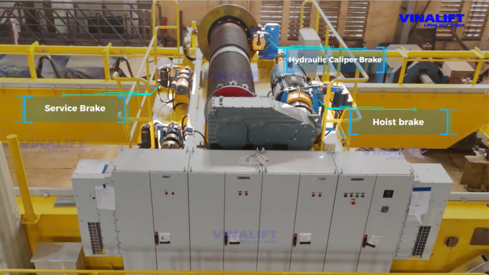
According to the configuration widely applied in the metallurgical industry, the system includes two independent braking layers operating at different positions in the drive chain.
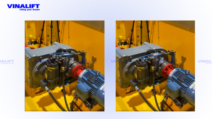
First protection layer: Hoist brake
The first layer is the hoist brake, also known as the service brake. These brakes are installed on the motor shaft or high-speed shaft of the hoisting system. Their functions are to:
- Control lifting and lowering movement.
- Support acceleration and deceleration.
- Stop the load during normal operating cycles.
- Perform the load-holding braking function under daily working conditions.
In metallurgical applications, one hoisting mechanism is usually equipped with two independent brake sets instead of only one brake set. This arrangement creates braking redundancy from the first level to improve operating reliability. However, this protection layer still depends on the stability of the gearbox, coupling, and the entire mechanical drive chain.
Second protection layer: Emergency caliper brake
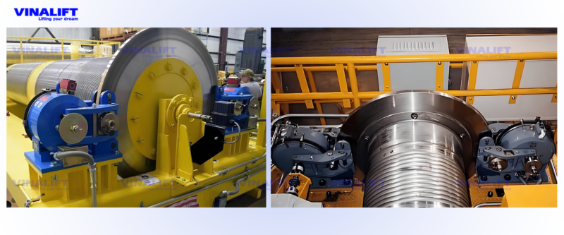
If the first layer protects the system under normal operating conditions, the second layer exists to respond to serious failures. The emergency brake is installed directly on the rope drum flange, the final position of the drive chain before the load is suspended on the hoisting rope system.
Because the brake is installed directly on the drum, even if the motor fails, the gearbox is destroyed, or the drive shaft breaks, the system still has the ability to lock the drum directly and prevent the load from continuing to move. The brake type commonly used in this protection layer is the Hydraulic Emergency Caliper Brake, which clamps directly onto the outer flange of the rope drum using hydraulic force and operates independently of the motor–gearbox drive chain. For ladle crane applications, the second braking layer is typically specified to act directly on the rope drum or drum flange so that load-holding capability is maintained even if the motor, coupling, gearbox, or drive shaft fails. This requirement should be verified against FEM 1.001 duty classification and the applicable project safety specification.
See more: [Single-failure proof design philosophy in ladle cranes] — an analysis of the complete six-layer Single-Failure Proof protection architecture, in which the multi-layer braking system is Layer 4.
Fail-Safe Principle
One of the most important requirements of ladle crane safety in a metallurgical environment is that the system must maintain load-holding capability even when the energy supply is lost. That is why both the hoist brake and emergency brake are designed according to the fail-safe design principle. Unlike conventional thinking, the system does not need electricity to brake; it needs electricity or hydraulic pressure to release the brake.
In other words:
- Closed by spring force.
- Released by electricity or hydraulics.
When the crane is operating, the energy source keeps the brake in the open state. When an incident occurs, such as power loss, hydraulic pressure loss, or control signal failure, the energy maintaining the open state disappears. At that moment, spring force automatically acts to close the brake and hold the load. This is the foundation of every modern molten steel load protection system.
When the emergency brake is activated
According to the design philosophy of modern metallurgical crane systems, the emergency brake does not operate continuously but is activated only when the system detects a hazardous condition.
Typical situations include:
- The drum enters an overspeed condition.
- The system detects a fault related to the hoisting rope.
- The operator activates the emergency stop (E-stop) button.
- The entire system loses power.
In these situations, the objective is no longer to maintain production, but to maintain load control and prevent the risk of load drop.
The role of Multi-Layer Braking Protection
The greatest value of Multi-Layer Braking Protection does not lie in the brake itself, but in its ability to resist single-point failure scenarios. When the load is still safely held even if the gearbox or drive system fails, the plant significantly reduces the risk of:
- Unplanned line shutdown.
- Damage to process equipment.
- Extended production interruption.
- Risk to personnel.
- Post-incident recovery costs.
For modern metallurgical plants, the ability to maintain load control under abnormal conditions is often far more important than adding a few more tons of nominal lifting capacity.
VINALIFT’s practical implementation
During technical consulting for metallurgical projects, VINALIFT’s engineering team has observed a clear shift in the way EPC Directors ask technical questions: no longer “how many tons can the crane lift,” but “what happens if the gearbox fails in the middle of a lifting cycle” and “how does the braking system respond when sudden power loss occurs.” That is the right way of thinking — and it is the way VINALIFT builds its design before customers even ask.
80/20 T Double Girder Overhead Crane | Specialized Lifting Solution for Metallurgical Plants
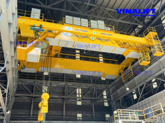
Context: The slag workshop and HRC1 hot rolling line operate continuously 24/7, duty class A6/M6, with ambient temperatures frequently exceeding 60°C. The equipment must maintain verified load-holding capability throughout the work shift, with no tolerance for unplanned downtime.
Challenge: Hoa Phat required the braking system to be independently verified before delivery — including physical testing of emergency brake response in simulated power-loss and overspeed scenarios, not only document-based inspection.
Implemented solution: VINALIFT equipped the crane with a complete two-layer braking system: two independent service brake sets on the high-speed shaft, each with braking torque rated at 150% of the rated motor torque, combined with a hydraulic emergency caliper brake clamping directly onto the rope drum flange and operating according to the fail safe design principle. The entire system was physically tested at the workshop with third-party witness before delivery.
Steel industry — 10 t gantry crane — Thai Nguyen Steel Plant, TISCO
Practical implementation shows that system reliability is not determined by the strongest brake, but by the final protection layer that still functions after failure has already occurred. That is also why modern molten steel handling solutions are always built on a multi-layer redundancy philosophy and fail safe design principle from the design stage.
Conclusion
In a metallurgical environment, the greatest risk is not that one brake fails. The greatest risk is that the entire load-holding capability depends on only one single brake. That is why Multi-Layer Braking Protection has become an almost mandatory requirement for modern ladle crane systems. When the hoist brake and emergency brake are arranged as independent protection layers, the system still maintains load-holding capability even when part of the drive chain has lost its function.
At VINALIFT, this philosophy does not stop at the design drawing. It is physically verified through workshop load testing of the braking system and FAT records signed before the equipment leaves the factory — from Hoa Phat Dung Quat to steelmaking plants in Argentina and the United States. Every braking system delivered from the factory is a commitment made with engineering and honor that your final protection layer will never fail when you need it most.
Request a braking system architecture diagram and a 30-minute technical review with a VINALIFT engineer
If you are preparing a technical specification for a ladle crane or evaluating a supplier’s technical dossier, VINALIFT’s engineering team is ready to provide a practical two-layer braking system architecture diagram and work directly with you to assess whether the current supplier’s braking solution is sufficient to protect against gearbox failure or total power-loss scenarios.
Hotline: (+84) 39 341 6686
Email: contact@vinalift.vn
